| Top Level: |
|
       |

| Peer Level: |
          |
|
|
Child Level:
 |
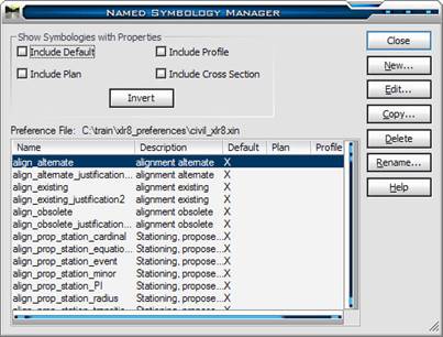
Named SymbologyNamed Symbology is managed from the Symbology Manager. 1. Select InRoads>Tools>Named Symbology Manager
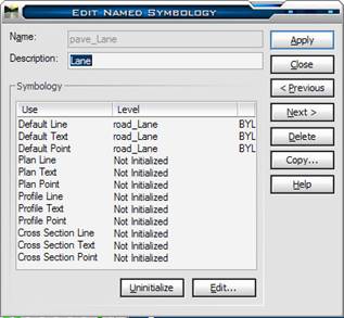
This may look intimidating, but it is not really that complex. Everything InRoads displays can be segregated into three types of elements: Linear elements, Points, and Text. InRoads, like Civil Engineers, display three Views of objects: Plan/3D, Profile, and Cross Section.
Three types multiplied by three views equals nine permutations. In most cases, an object is either only displayed in one View or the symbology requirements are identical in all views. In these cases the settings only need to be defined for Default Line, Default Point and/or Default Text. Definition HierarchyHow does InRoads read the Named Symbology definition? First, an InRoads command displays graphics in Plan, Profile, OR Cross Section and looks to the appropriate View entry. If there is a definition, InRoads uses it. If the appropriate definition is Not Initialized, it looks to see if the appropriate type is defined in the Default entries. If so, it uses that definition.
For example, if a Profile command is looking to display a Point it looks for a Profile Point definition. If it Profile Point is not defined, it looks to Default Point. If that is not initialized, it will not display the profile points.
In this way, Named Symbology can limit unnecessary displays in InRoads (although the preferred ways are through Feature Style Display properties and Feature Filters). For example, it almost never advisable to project Random points onto a profile. If the Random Point Named Symbology is Not Initialized for Profile Point and Default Point, you will not have to worry about 100,000 points accidentally projected onto a profile.
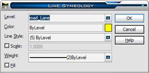
Line Symbology3. In the Symbology list, double-click on the Default Line object.
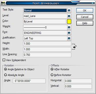
Text Symbology
Note: maintaining text size consistency throughout InRoads can be a challenge. Make sure that if you create Named Symbology with Text definitions that you are conforming to your organization’s text standards (this is where an InRoads Administrator is wonderful to have).
When InRoads displays Text it reads the Height and Width
values and multiplies by the Global Text Scale Factor (found under
InRoads>Tools>Options>>Factors. In this way, individual settings do not need to
be defined for every drawing scale you use.
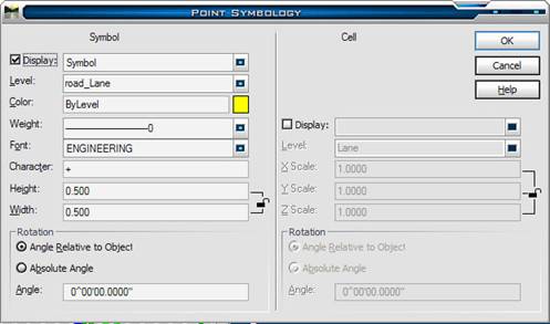
Point Symbology
Non-cell representations of points are multiplied by the Global Text Scale Factor (NOT the Cell Scale factor!). |
|