| Top Level: |
|
       |

| Peer Level: |
    |
|
|
Child Level:
 |
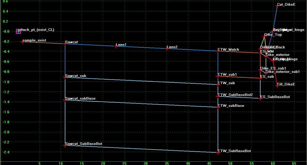
Templates - Widening: Auto NC or Match SlopeOriginally for I805-Managed Lanes, but we moved from AutoMatch to Controlled by Super Diagram. KHA_templates.itl: __widening_components/conglomerations/Caltrans_Auto_NC_or_Match/ The Exterior Widening Templates are as follows:
The left side template is a copy of the right side template: the difference is in the definition of the Display Rules. Slopes are defined in Templates as being positive when going upwards from left to right. Our New Pavement Slope is, by this definition, 2.5% on the Southbound side and -2.5% on the Northbound side. InRoads translated the Rules properly when dragging the right into the blank left template (with the Reflect option ON). All Display Rules for the Left are prefixed by "Left_" in case the Left and Right get merged eventually. How it WorksThe shot below shows a "template for the widening template" (templates are tweaked a lot, this is probably already out of date).
Attachment PointThe attachment point (where the template attaches to the Horizontal and Vertical Alignment (or surface feature)) "attach_pt_(exist_CL)" is where the template is attached to the Horizontal and Vertical Alignment (or surface feature). It has no bearing on the resultant model other than the stationing at which templates are dropped perpendicular to. You typically want to drop templates along the same alignment that you are cutting sections from. Using the sawcut alignment as the horizontal alignment tends to lead to kinky results (they tend not to have curves). Sampling the Existing SurfaceThe Sawcut point and "sample_exist" point are both Projected to the Existing Surface. The Slope or "Vector" between them are used as the slopes for the ETW and ES points. Additionally, a number of Display Rules use this slope for logical processing. The Sawcut point should be constrained horizontally to the Sawcut alignment using the Point Controls command in Roadway Designer. If the Sawcut alignment has vertical information the Point can be constrained Vertically to the sawcut Vertical Alignment, but this is NOT the preferred solution as the sawcut is a proposed feature and may be shifted horizontally due to design needs. Survey information along a probable sawcut line is better fed into a surface. Horizontal Shifts or Surface improvements require no changes to the setup if the Survey Point is Project to Surface. The "sample_exist" point is should be offset horizontally into the existing roadway some distance that gives are relatively consistent slope extension. If there are "lane shots" in the existing surface this will often cause a break in existing cross slope. The "sample_exist" point should most often be set to sample to the outside of the break (otherwise your resulting slope is more of a weighted average of cross slopes). Pavement ComponentsThe next Component is the Pavement component. It's slope is set using the Vector-Offset constraint on the Lane1. The vector is "sample_existing" to "Sawcut" as mentioned above. The offset is zero to match slope (if we wanted to provide a half percent break, we could set the Offset to 12'x0.5%= -0.06 feet). The remaining points in the component use the Sawcut-Lane1 vector to match its slope. The Shoulder Component slope is constrained to 5% in this template, at super ranges, greater than (absolute) 5%, the slope should be defined as the Lane2-ETW vector. The generic ~.itl/_end_conditions/molecules/CalTrans/Dike_E_2:1_CaseFR template is attached, unmodified, to the outside of the shoulder component. Display Rules:Here's a table describing the slope logic for the templates:
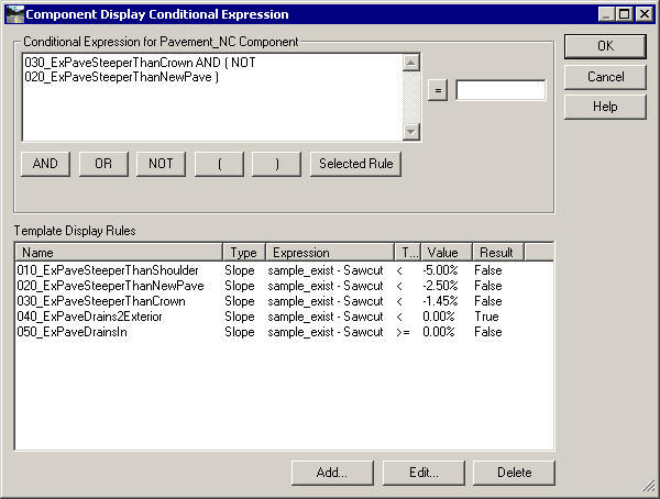
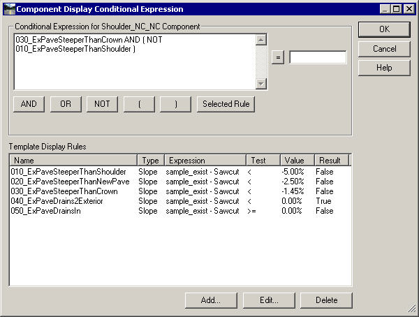
Display Rules Set provide the logical mechanism for switching between Matching and "Hard" Slopes.
The Match Slope Pavement component displays otherwise. All of the components to the exterior of the Pavement components ( are children (descendents) of the appropriate Pavement component: if a Pavement component does not display, none of its children do. Shoulders are either 5% or matching, condition expressions are set up for each.
|
|