| Top Level: |
|
       |

| Peer Level: |
    |
|
|
Child Level:
 |
Templates - Ramps: Search and BuildThere are a wide variety of ways to build walls in the model. The list below starts with the
I've set up a "mostly automatic" template in the main template library: "_end_conditions/wall_at_feature" which can be a included in a "mainline" or ramp template or pushed along a graphic (an existing hinge point, for example). Here’s what it is designed for:If you have intermittent cut or fill retaining walls along a corridor you can push this template the whole way without having to know where the retaining walls begin or end or whether they are cut or fill. You can incorporate this solution into a mainline/ramp template by replacing the 2:1 Cut and Fill components with this template.
Pre-requisitesYou must have a surface with the horizontal locations of the walls (vertical is not necessary). The Feature Styles of the wall features must be "struc_Walls_horizontal."
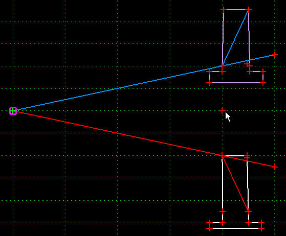
How it WorksDuring a template drop, the template
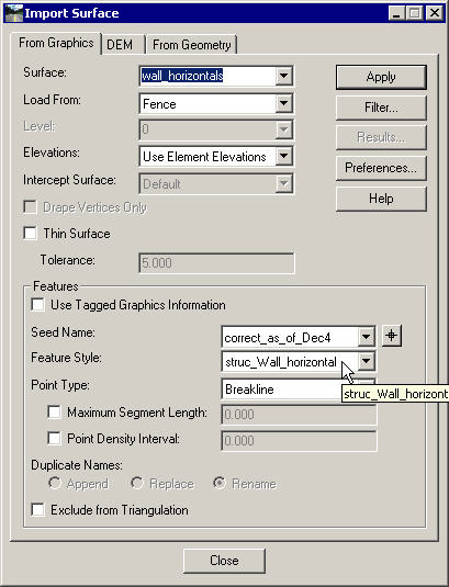
Creating the "wall horizontals" surfaceHow do you get a surface with “struc_Wall_horizontal” features in it?
The Beauty of Cross Section Wall ComponentsThe cut and fill wall components are superfluous outside of the beauty they add to the cross sections. The have two points that tie into the "work" components (cut_wall and fill_wall). Feel free to make even more beautiful walls by adding points and moving them around as necessary. Note: the underground features should have a feature style like "struc_Wall_subgrade" so that they are easily filtered out of displays. Also, it's relatively simple to have the wall foundations scale automatically with the height of the wall, so if that's a need on your sheets, keep that in mind. Quirks and CaveatsThe template searches the Active Surface for the feature styles. If you have a "wall horizontals" surface and it's not Active, the wall search will fail and the template will use the typical 2:1 solution. Because the Active Surface has to be the "wall horizontals" surface, the target surface for the wall daylights had to be specified by Name rather than <Active>. If your walls don't intersect it's because the end condition components are targeting the <Active>. This is rectified, by selecting the existing surface in the Component target list. If you're using InRoads Apply Template the "Design Surface" (the destination or recipient surface) field tends to default to the active surface. You'll dump your new stuff into the "wall horizontals" surface accidentally. If you're editing it will be much easier visually if you edit the "wall_check" point and set the offset to something like 8 ft. It's currently set very tight because the template only works if the wall horizontal is to the outside of the check point (hence the visually ugly tightness).
|
|