|
InRoads Workflow Library
GLF - Creating Retaining Walls (3D)
Command Overview
3D linestrings: It's what we do. It's what Generate Longitudinal
Feature (GLF) does. InRoads>Surface>Design Surface>Generate Longitudinal
Feature.
Given a 3D linestring, if you want another 3D linestring without running a
template, GLF is the command for you.
This lab is about creating a retaining wall from a hinge point.
Tool Pre-requisites
A 3D linestring to start with. A 2D element to go to (can be 3D, but
only the 2D part is used).
Workflow Overview
- Establish your 3D starting linestring (hinge point?)
- Have an element (2D linestring?) defining the 2D location of the wall
- Use GLF to establish the 3D bottom (or top) of wall; Horizontal Mode is
"Along Selected Feature," Vertical Mode is typically Transverse Slope.
- Use GLF to establish the 3D top (or bottom) of wall; Horizontal Mode is
"Offset from Primary Feature," Vertical Mode is "Drape" to the surface.
- You now have a wall. You may have cleanup to do outside the wall
(often you have a daylight line from previously daylighting at the exterior
Transverse slope). This typically involves partial deletes of all new
features exterior to the wall (essentially you're putting the existing
surface back in outside the wall).
Detailed Runthrough
I'm using the data in Exploring InRoads.
We'll arbitrarily through in a wall in a wide cut area.
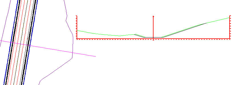
I've used my random engineering skills to through a 2D linestring across the
wide cut area (actually, I snapped to the daylight lines at ends, so they're at
elevation. The middle two vertices are at the active Z, whatever that is.
The elevation of the linestring is irrelevant).
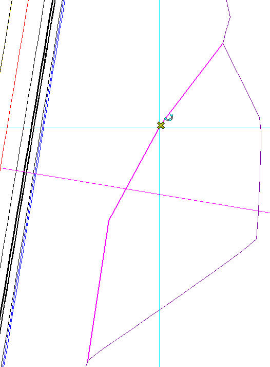
1. Establish your 3D starting linestring (hinge point?)
I'll use the out exterior ditch bottom (the 3D feature immediately
interior to the new 2D line) as my primary feature (the 3D starting point).
2. Have an element (2D linestring?) defining the 2D location of the
wall.
(Described above)
3. Use GLF to establish the 3D bottom (or top) of
wall; Horizontal Mode is "Along Selected Feature," Vertical Mode is
typically Transverse Slope.
At the "Identify Element Used to set Horizontal Offset" select
the new 2D linestring.
|
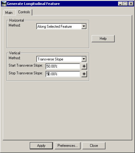 |
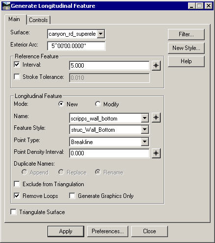
The Main tab contains the overhead (the new Feature's
Properties).
What Surface to put it in
The Name
The Style (we have a couple styles for walls).
|
 |
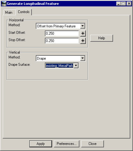
4. Use GLF to establish the 3D top (or bottom) of
wall; Horizontal Mode is "Offset from Primary Feature," Vertical Mode is
"Drape" to the surface.
InRoads Surfaces cannot triangulate vertically, so there has to
be some Horizontal Offset. You can use some almost vertical
offset or go to the back of wall.
|
 |
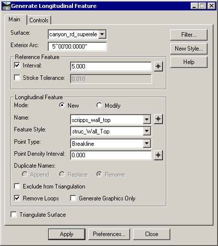
The Main tab contains the overhead (the new Feature's
Properties).
What Surface to put it in
The Name
The Style (we have a couple styles for walls).
|
 |
5. You now have a wall. There will need to be some cleanup outside the
wall. The Fill Line at the top of the original 2:1 slope is no longer
valid.
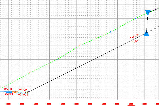
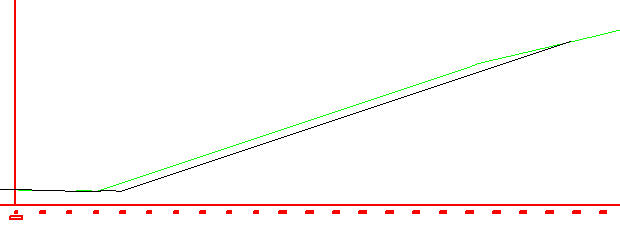
Whoops, I put a 50% Transverse Slope in a section where the existing slope
was around 30%. The commands still worked, though the engineering needs
work.
|